
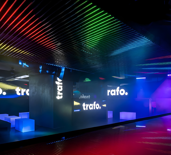
The concept and technical design of an LED installation with digital pixel controllers, demonstrated through its application at Trafo Music Bar.
Assignment
Cover the ceiling of Trafo Music Bar with LED strips made of aluminum profiles, into which RGB LED strips (60 LEDs/m) will be inserted and covered with transparent diffusers. Individual pixels will be controlled separately, allowing us to achieve a dynamic design with the ability to control all pixels via software or a media server connected to the lighting console.
Dividing the ceiling into 10 smaller blocks
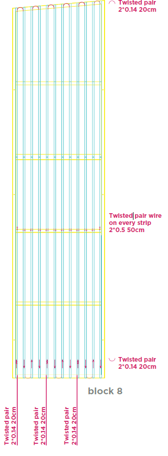
In many large projects, it is essential to think in terms of smaller blocks, which are then assembled on-site into a single unit. We have divided the entire ceiling into 10 separate blocks, each of which functions as a standalone unit.
Each block has its own control unit—an LED Ethernet Controller 3 (LEC3)—and power supply. One block contains 12 rows of RGB LED strips (IC WS2812, 60 LEDs/meter, plastic cover). Each strip was cut to a length of 3415 mm.
Aluminum Profile
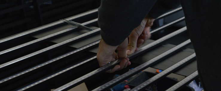
We decided to use a thin black aluminum profile measuring 20 mm × 10 mm × 3000 mm. The client chose to place a transparent diffuser over the LED strips to protect them from accidental damage (since people can get a little wild at parties…).
For a smooth transition between individual LED pixels, we recommend choosing an opaque or frosted diffuser and a profile with a depth of at least 25 mm. However, the client opted for a transparent diffuser, which results in the individual LEDs being visible.
resulting in the individual LEDs being visible.
Signals
The signal starts in the lower left corner and follows a “zigzag” pattern through all 12
LED strips to the lower right corner, where the signal ends (see the arrows illustrating
the signal flow from one row to the next). Based on our experience, we recommend using
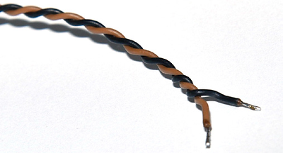
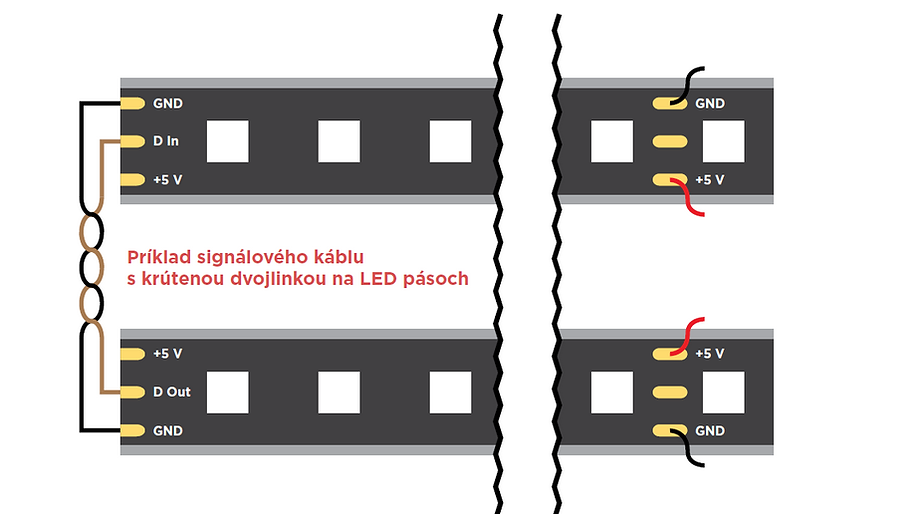
twisted-pair cable for the signal. This provides better shielding against other signals, such as Wi-Fi. Twisted-pair cabling – 2 x 0.14 mm We recommend using 2 x 0.14 mm cable for the signal.
Power Supply
Power can be supplied in many ways. However, before any installation, it is necessary to
answer two key questions:
- What would be the ideal solution for this building?
- **How can the power supply be set up simply, in a few steps,**without voltage drop?
What do we know about voltage drop?
You should always follow the manufacturer’s instructions and understand voltage drop.
The basic fact about voltage drop in a 5V RGB LED strip is that after 2.5 meters, you start to lose brightness. Additionally, the colors will be less vibrant, and you may notice a difference between the beginning and end of the LED strip.
So what can we do?
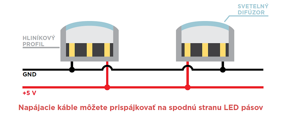
We simply connect the LED strips in the first third. At the 1/3 mark of the profile, we drilled small holes for the cables and soldered the LED strips from the back. The first 1/3 is powered from the back, and the remaining 2/3 are powered from the front. The longest section is 2100 mm, which is less than 2500 mm. We recommend using a 2 x 2.5 mm cable.
Selecting the Right LED Controller
The client requested a digital dynamic ceiling that can be controlled in three ways:
• LSS software
• Control via Art-Net™ – third-party software (Resolume)
• Option to control using a lighting console
That is why we chose the LED Ethernet Controller 3 (LEC 3)

How many LED controllers do we need?
Each block contains a total of 12 rows of LED strips with a total length of 3415 mm.
The calculation of the number of RGB pixels in one block is as follows:
3.5 m x 60 RGB pixels/m x 12 rows = 2520 RGB pixels.
For simplicity and organization, we decided to divide the 12 rows into 4 groups of 3 rows each.
We made this decision because the LEC 3 has 4 SPI outputs. This makes it easier to identify a specific output in case of any issues.
Placing all blocks into a single large unit
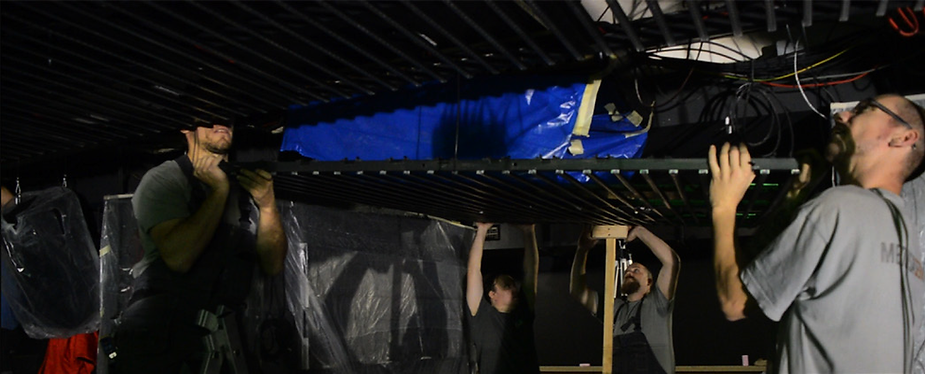
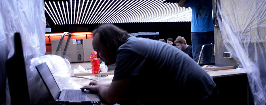
This part was completed on-site during installation. We attached the blocks to the ceiling using
large screws. Precision is very important to ensure that the blocks are placed
exactly in the right spot and all pixels form a continuous grid (screen).
Connecting all the blocks
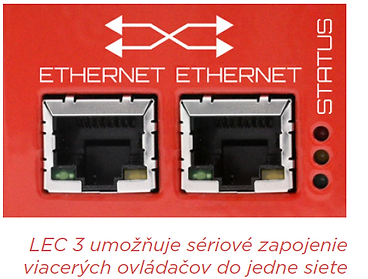
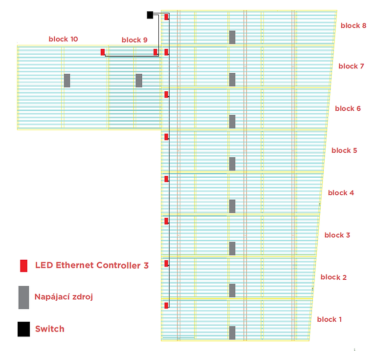
Each block was daisy-chained to the next, creating a network of 10 controllers. This was possible because the LEC 3 controller has a built-in Ethernet switch with two RJ-45 ports.
The complete diagram looked like this, starting
with Block 1 and ending the chain at Block 10. We connected an Ethernet cable from the main switch to the first LEC 3 controller, thereby creating a network:
• A computer with LED Strip Studio (LSS) software installed
• A computer running third-party Resolume software, which generates a video stream
and adds the ability to control the LED ceiling via Art-Net™
• A lighting console
LED Mapping
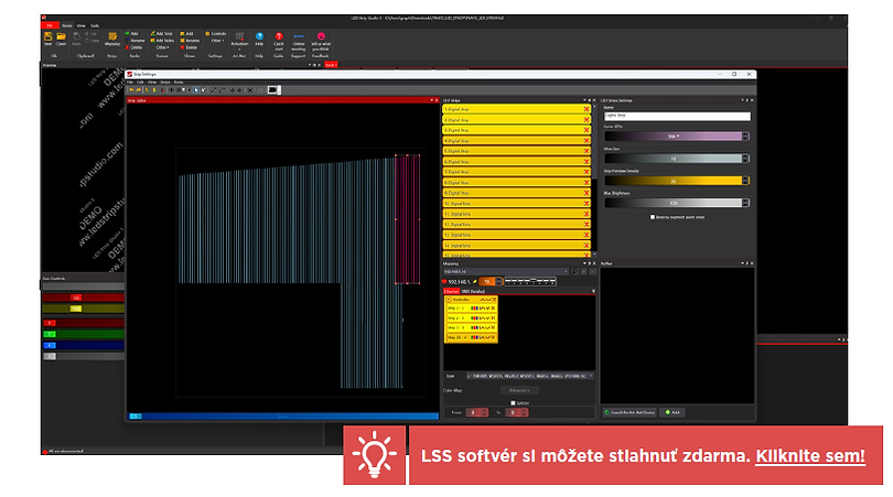
After connecting all ceiling blocks to the LED controllers and power supplies, the next step is configuring the LED strips to precisely project the video content—this process is called mapping. For this task, JB, our lead hardware developer, used LED Strip Studio (LSS) software. This software simplifies mapping compared to conventional methods thanks to its user-friendly interface.
The process in LSS was quite simple:
1. JB drew 10 groups of LED strips (since the ceiling consists of ten blocks)
2. He assigned a number of LED pixels to each strip – as indicated on the installation plan, each row of LED strips had a slightly different length and therefore a different number of LED pixels
3. Finally, JB assigned a separate controller to each group of LED strips.
4. Done – Mission accomplished!
An interesting combination of Resolume and LSS software
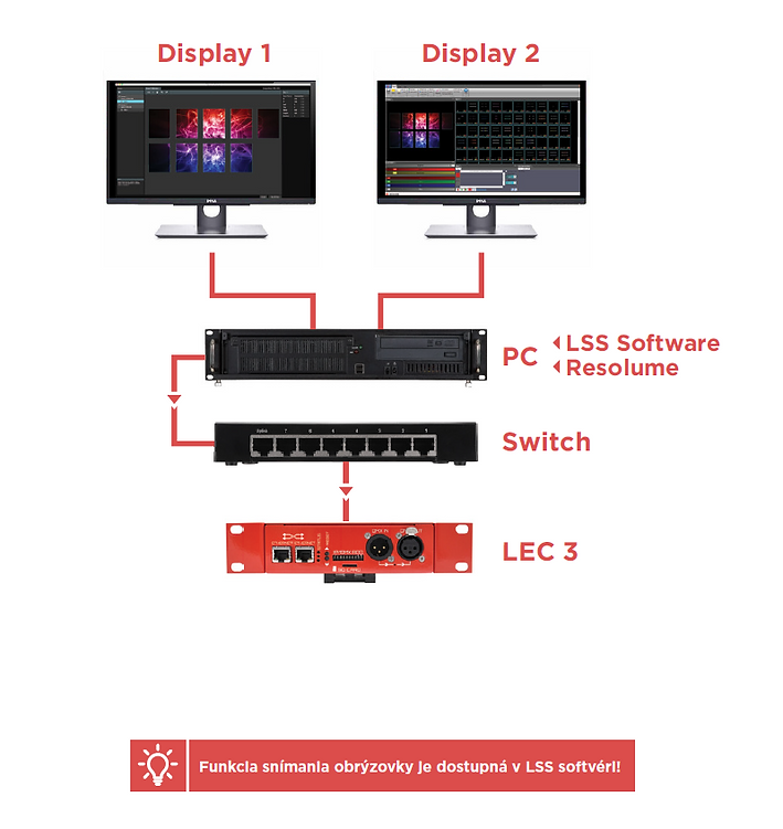
We decided to approach the installation in an original way. Resolume generates output for the LED screens and LED ceilings. The output for the LED screen is visible on Display 2, while the output for the LED ceiling is on Display 1. What’s unique is that the LSS software captures the image from Display 1 and sends the signal to the LEC 3 controllers.
Done in 60 seconds
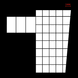
A super-fast way to calculate and map LED strips. This tool in the LED Strip Studio software helps you
calculate the number of LED strips needed for your installation and automatically generates a layout for the entire LED installation. All you need to do is import an image of your installation plan, preferably as a black-and-white silhouette (see image on the right).
Step 1
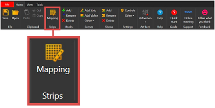
Go to the home panel. Click the Mapping icon and open the Strip Settings window.
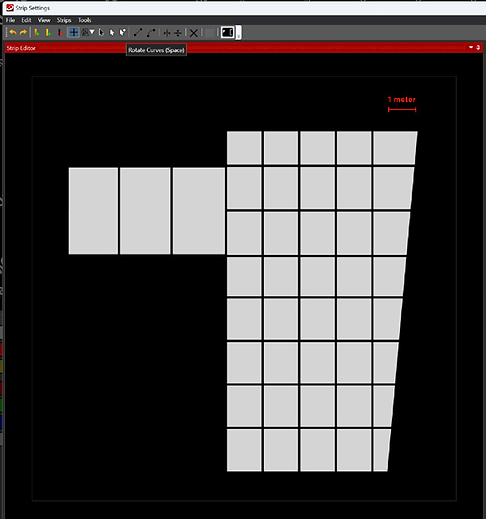
Step 2
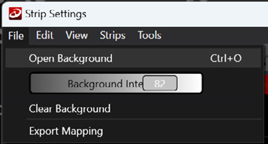
In the Strip Settings window, go to File > Open Background and select an image.
Step 3
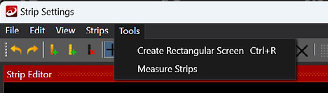
After importing the image, go to Tools > Measure Strips (Tools > Measure strips)
Step 4
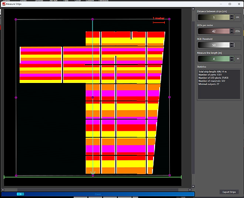
In the Measure Strips window, set the Measure Line (green line) as the reference point for the scale and enter the actual length in the Measure Line Length field. You can also adjust the orientation of the LED strips by dragging one of the purple points.
Step 5
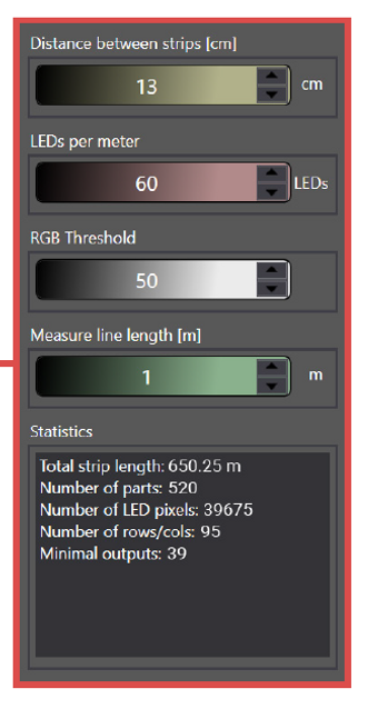
Set the remaining parameters for your LED installation. You can ignore the RGB Threshold, as the image consists only of black and white. The software will recalculate all parameters and display the results in the Statistics field.
Step 6
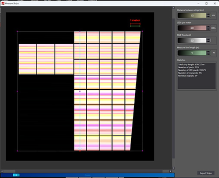
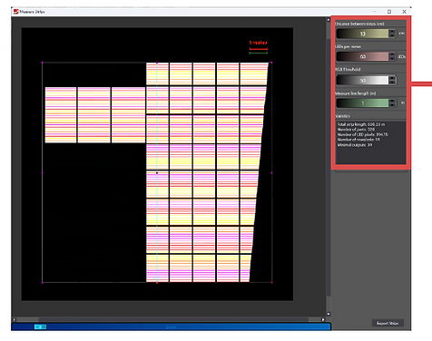
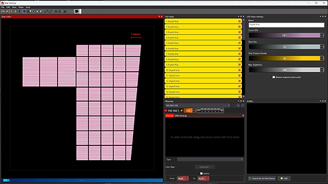
If you are satisfied with the result, you can click the Export Strips button in the lower right corner. The LSS software will automatically generate the mapping for all LED strips.
Step 7
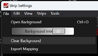
In the Strip Settings window, go to File > Clear Background to remove the image
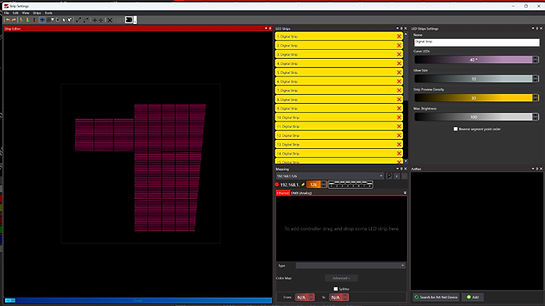
Step 8
Close the Strip Settings window and run one of the video effects. In the preview panel, you will be able to see the animations running on the LEDs
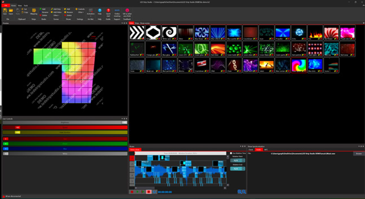
Congratulations! You’ve just learned how to quickly calculate and map an LED installation using the Strip Measurement tool! We’re here to provide you with the best solution for your project.
Why divide a large LED ceiling into smaller blocks instead of one big area?
Dividing into blocks keeps each section self-contained with its own controller and power supply. If something goes wrong in one block, only that section is affected — not the whole ceiling. It also makes installation much more practical since you can build, wire, and test each block in the workshop before bringing them on-site and assembling them into the complete installation.
Why does the signal follow a zigzag pattern instead of going straight across the ceiling?
The zigzag (serpentine) pattern means the data signal from one strip flows directly into the next strip at its nearest end, without needing a long return cable. If each strip’s signal ended at the far end and you had to run a cable all the way back to start the next strip, you’d need much more cable and create a wiring mess. The zigzag keeps data flow continuous and cable runs short.
Can the same LED ceiling be controlled by multiple software systems at once?
Yes — the Trafo Music Bar installation in this guide does exactly that. LED Strip Studio software, Resolume (a VJ/media server application), and a lighting console all control the same ceiling via Art-Net. Each system outputs Art-Net to the LEC3 controllers, and operators can hand control between systems as needed. This kind of multi-source flexibility is one of the reasons Art-Net over Ethernet became the industry standard.
How do I avoid voltage drop on long strips in a ceiling grid?
Inject power at multiple points along each strip rather than powering everything from one end. For 5V WS2812B strips, inject at the one-third and two-thirds points of each profile as described in this guide — that way no section is more than about 2 meters from a power connection. This keeps voltage consistent across the entire ceiling and prevents the color shift and dimming you’d see at the far end of a long unpowered run.
What’s the Measure Strips tool in LED Strip Studio and when do I use it?
The Measure Strips tool automates the strip layout calculation for grid-style installations. You import a black-and-white silhouette of your installation plan, set a scale reference, and the software calculates how many strips fit the area, their lengths, and generates the complete pixel mapping automatically. It turns a calculation that would take hours manually into a few minutes of setup — especially useful when strips have slightly different lengths across a large grid like a music bar ceiling.